 |
||||||||
|
||||||||||||||||||||||||||||||||||||
|---|---|---|---|---|---|---|---|---|---|---|---|---|---|---|---|---|---|---|---|---|---|---|---|---|---|---|---|---|---|---|---|---|---|---|---|---|
|
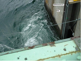
| Laforge-2
Project Plant size - 304 MW |
In
1997, Hydro Quebec measured turbine discharge at the Laforge-2
low-head plant with both the current meters and the ASFM. Three frames were used, with 10 current meters mounted on each of four rows. The ASFM transducers were mounted near the top of only one of the frames. Measurements were taken simultaneously at various operating conditions using:
|
|
 |
Les Cèdres Plant size - 135 MW |
Les Cèdres powerplant is situated on the St-Lawrence. The geometry of the water intake of each of its 17 units corresponds well to the typical shape for which the ASFM was developed: short and irregular. The intake comprises three separate entrances, each of which are divided in two vertical sections by a two foot thick horizontal pier.
|
 |
Coteau 1 spillway |
The Coteau 1 spillway is part of the Beauharnois development on the St-Lawrence river. It is used to control the flow going to Les Cèdres powerplant situated slightly downstream. Model tests were performed to determine the spillway flow, however, a better accuracy was required for the plant operation. Publication: presented at HydroVision 2008 |
 |
Rapides-des-Quinze Plant size - 95 MW |
Rapides-des-Quinze is not a typical low-head power plant because the two intake bays converge to a single penstock and a standard scroll case. As most of the Gibson pressure taps were blocked, the current meter method was used in the intake. In 2002, the current meter frames were placed in the stop log slots, upstream of the trash racks. As the ASFM transducers were placed on top of the frames, they were also upstream of the trash racks. Publication: presented at HydroVision 2008 |
 Click image to enlarge Click image to enlarge |
La Grande-1 Plant size - 1436 MW |
For the 2003 comparison between the current meter and ASFM discharge measurements at La Grande-1, the ASFM transducers were mounted at the top of the current meter frame, so the velocity profile was only partially sampled. The results showed a difference between the two methods of around 1.8 %, with the ASFM underestimating. By using filtering technique to account for vibration of the frame and by changing the number of samples for each individual velocity calculation, this difference was eliminated. CFD simulations of the flow in the intake showed significant velocity variation due to the wake of the main structural members of the trash racks. This was confirmed by both the ASFM and current meter methods.
Publication: presented at IGHEM 2004, HydroVision 2008, HydroVision 2011 More recently, a special version of the ASFM Monitor has been used with three paths installed vertically at the end of the spiral case, chosen because this location is the farthest from the intake and thus can limit the influence of velocity profile changes. The other methods tested were Acoustic Time of Flight, Acoustic Doppler and various pressure difference sensors on the stay vane. The first series of tests has been performed to compare and calibrate the ASFM Monitor measurements with previous results obtained in 2005 with the Current Meter method. The second series of tests has been performed to verify the influence of the operation of adjacent units. The maximum Publication: presented atHydro 2009, HydroVision 2011 |
 |
Rocher-de Grand-Mère Plant size - 220 MW |
The Rocher-de-Grand-Mère is a newly commissioned power plant on the St-Maurice river. The intake has two bays and the layout is typical of a modern design with a relatively smooth converging form. The discharge measurement method used for the acceptance test in 2006 was the current meter method, with 28 current meters mounted on each movable frame. The ASFM transducers were mounted near the bottom upstream edge of each end plate, around 30 cm above the lower row of current meters. Publication: presented at HydroVision 2008 Reprocessing of the data by using a low pass filter to remove the effect of current meters has shown a great improvement in the results from the ASFM methods even though this process has removed a large part of the spectral content of the acoustic signals; better results were found at high discharge where more of the signal was retained. Although the installation of the ASFM transducers on the same frame as the current meters allows making a comparative measurement at low cost, this should never override the need to have the ASFM transducers farther from the current meters. Publication: presented at WaterPower 2009, HydroVision 2011 |
 |
Rupert Control Structure Plant size - 220 MW |
The Rupert Control Structure is part of the river partial diversion project that will bring water to three existing power plants as well as to a new plant (La Sarcelle). Maintaining a minimum flow of water in the river bed for environmental purposes is so important that Hydro-Québec decided to monitor the discharge with two methods: the Acoustic Time of Flight and the ASFM Monitor. The two flow meters are installed in the central control spillway, with the transducers embedded in the concrete so that they are completely out of the flow. For the ASFM Monitor, eight paths have been installed about 9 m upstream from the gate. This position has been chosen as a compromise between the need to be as far as possible from the forebay in order to get enough turbulence and flow uniformity as well as avoiding flow recirculation close to the partially opened gate. The measurement took place in December 2009 and covered the full gate opening. Publication: presented at Hydro 2009 |

